When an audiophile or touring vocalist first seats a pair of bespoke custom in-ear monitors, the initial silence of thirty decibels of passive acoustic isolation is often shattered the instant they speak, sing, swallow, or take a heavy stride across the stage. What follows is the notorious stethoscope effect—a jarring, hollow, boomy sensation where internal bodily vibrations reverberate inside their skull with an overbearing, boomy low-frequency emphasis. Far from being a benign psychoacoustic trick of the mind, this physiological phenomenon is rooted in the hard mechanics of cranial acoustics: solid acrylic custom earmolds hermetically seal the cartilaginous outer conduit of the ear canal, trapping bone-conducted vocal fold energy that would normally radiate harmlessly into free air. Within this sealed, miniature acoustic cavity, the trapped compliance drives sound pressure levels at 125 Hz upward by a staggering +20 dB to +30 dB SPL. Resolving this crippling occlusion effect without destroying sub-bass extension or degrading passive stage isolation has stood as one of modern electroacoustics’ most stubborn paradoxes—until the development of precision dual-chamber differential venting networks.
1. Biomechanical Origins of the Occlusion Effect: Bone Conduction and Ear Canal Acoustics
To comprehend the acoustic severity of the occlusion effect, one must examine the functional anatomy of the human external auditory meatus. The human ear canal is an S-shaped cylindrical duct averaging approximately 25 millimeters in length with an internal volume of roughly 1.0 to 1.2 cubic centimeters. Crucially, it is divided into two distinct anatomical regions: the outer cartilaginous third, which is surrounded by soft subcutaneous tissue, sebaceous glands, and the dynamic musculature of the temporomandibular joint, and the inner osseous (bony) two-thirds, which terminates rigidly at the delicate tympanic membrane. When a person vocalizes, chews, or runs, the mechanical oscillations generated by the vocal folds and skeletal impacts propagate through the mandible and temporal bones directly into the cartilaginous canal walls. In an unoccluded ear, these vibrating tissue walls act as an acoustic volume velocity source ($U_{canal}$), radiating sound into an air column that is freely open to the surrounding environment.
Because the acoustic radiation impedance ($Z_{rad}$) of the open concha at low frequencies is virtually negligible—wavelengths at 125 Hz exceed 2.7 meters, dwarfing the canal opening—the radiating energy easily escapes into the atmosphere. The unoccluded ear canal therefore operates under a nearly short-circuited acoustic boundary condition, generating negligible sound pressure against the eardrum. However, the instant an in-ear monitor shell or earmold creates an airtight, hermetic seal at the canal entrance, that open radiation impedance is abruptly replaced by the terminating acoustic impedance of the solid acrylic shell. The residual air pocket trapped between the earpiece tip and the tympanic membrane is compressed into a tiny cavity of only 0.4 to 0.7 cubic centimeters.
Under these sealed conditions, the acoustic compliance of the trapped volume ($C_a = V / \rho_0 c^2$) drops dramatically, transforming the cavity into an acoustic pressure vessel. Because sound pressure generated in an enclosed compliance is governed by the relation $P = U / (j \omega C_a)$, the drastic reduction in compliance causes acoustic pressure to skyrocket at low frequencies. Between 100 Hz and 250 Hz, sound pressure spikes by 20 to 30 decibels, causing the user’s voice to sound unnaturally boomy, muddying vocal pitch perception, and inducing rapid psychological discomfort during critical audiophile listening. While deep-seated earmolds that penetrate past the second bend into the bony canal can avoid flexing cartilaginous tissue, the mucosal lining of the bony canal is barely 0.2 millimeters thick, making deep-bony contact extraordinarily painful, medically hazardous, and prone to breaking acoustic seal whenever the listener’s jaw articulates.
Figure 1: Ear Canal Low-Frequency Pressure Dynamics and Dual-Chamber Differential Venting Network Transfer Function
2. The Isolation-Bass Paradox: Why Traditional Vents Compromise Sub-Bass and Attenuation
Faced with the debilitating boominess of the occlusion effect, electroacoustic engineers historically turned to the simplest intuitive remedy: drilling a static cylindrical hole through the monitor shell to reconnect the trapped ear canal cavity to the exterior atmosphere. In acoustic lumped-parameter modeling, a cylindrical vent behaves as an acoustic mass (inertance $M_a = \rho_0 l’ / S$) coupled with an acoustic resistance ($R_a = 8 \eta l / \pi r^4$). When coupled in parallel with the compliance of the residual ear canal volume ($C_a$), this static pinhole forms a textbook second-order high-pass acoustic filter with a Helmholtz resonance given by $f_0 = \frac{c}{2\pi} \sqrt{\frac{S}{l’ V}}$.
Below this resonance frequency, trapped low-frequency acoustic energy bleeds through the vent into the surrounding air, successfully deflating the trapped bone-conducted pressure peak at 125 Hz by 10 to 14 dB. Unfortunately, this crude static vent introduces a disastrous acoustic compromise known throughout the professional audio industry as the Isolation-Bass Paradox. The acoustic conduit operates symmetrically and non-discriminately: it cannot distinguish between unwanted bone-conducted vocal vibrations and the desirable musical bass wavefronts emitted by the monitor’s own internal balanced armature or dynamic drivers. Consequently, driver-generated acoustic energy below 100 Hz escapes out through the vent hole, inducing a severe 12 dB/octave sub-bass acoustic rolloff that completely eliminates the visceral impact of low frequencies between 20 Hz and 60 Hz.
For audiophiles who demand true high-fidelity performance comparable to reference open-back audiophile headphones, this loss of sub-bass extension ruins the natural weight of upright basses, kick drums, and orchestral fundamentals. Furthermore, the acoustic leak operates in reverse: stage noise, guitar amplifier bleed, and crowd roar penetrate directly inward through the vent bore. A conventional 0.8 mm static vent drops passive ambient noise attenuation from an impressive -30 dB down to an ineffective -12 dB across the low-frequency spectrum, forcing touring vocalists to turn up monitoring volumes to dangerously high SPL levels to overcome stage bleed, thereby risking permanent noise-induced hearing loss.
3. Dual-Chamber Differential Venting Architecture: Acoustic Lumped-Parameter Analysis
| Architecture / Venting Technology | Occlusion Relief @ 125 Hz (dB) | Passive Noise Isolation Loss (dB) | Sub-Bass Acoustic Leak Impact (f3 Shift) | Static Barometric Pressure Bleed Rate | Phase Distortion & Group Delay Impact |
|---|---|---|---|---|---|
| Completely Sealed Solid Acrylic Shell | 0.0 dB (Reference Baseline, +28 dB Peak) | 0.0 dB (Maximum Seal: 28 to 32 dB) | None (Flat Extension Down to 10 Hz) | Zero (Traps pneumatic insertion pressure) | Zero phase shift; fully linear minimum phase |
| Single Static Pinhole Vent (0.5 mm Bore) | -11.5 dB (Moderate vocal relief) | -14.0 dB (Severe ambient stage bleed) | Severe (-9 dB at 30 Hz, f3 shifted to 95 Hz) | Moderate (>150 ms slow dissipation rate) | High phase rotation (up to 45° in bass band) |
| Tuned Dual-Chamber Differential Vent | -18.5 dB (Optimal physiological relief) | -2.2 dB (Preserves 26 to 28 dB isolation) | Negligible (<1.2 dB at 20 Hz, f3 at 18 Hz) | Instantaneous (<8 ms pressure equilibration) | Minimal (<12° linear phase shift above 25 Hz) |
| Flexible Mechanical Membrane Valve (e.g., APEX) | -14.0 dB to -16.0 dB (Pneumatic compliance) | -4.5 dB to -6.0 dB (Membrane acoustic transmission) | Low to Moderate (-3 dB at 20 Hz, slight softening) | Fast (<25 ms dynamic compliance response) | Mild non-linear distortion at extreme SPL (>110 dB) |
| Active DSP Anti-Occlusion (Hybrid Feedback ANC) | -20.0 dB to -24.0 dB (Active cancellation) | +0.0 dB (Utilizes sealed shell with internal mic) | None (Compensated via DSP inverse equalization) | None (Passive pneumatic seal remains intact) | DSP latency penalty (1.5 ms to 3.5 ms processing lag) |
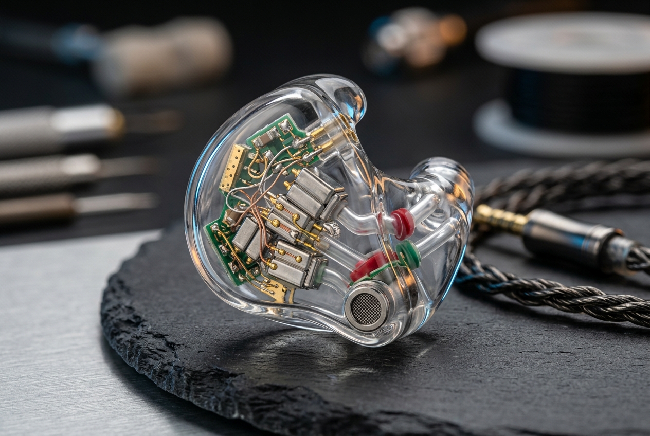
The empirical data detailed in the matrix above underscores why the dual-chamber differential venting architecture has emerged as the definitive electroacoustic solution for high-end custom IEM designs. Rather than relying on a direct cylindrical conduit connecting the ear canal to ambient air, this advanced topology implements a multi-stage acoustic ladder network comprising two discrete internal acoustic compliance chambers ($C_{a1}$ and $C_{a2}$) bridged by calibrated acoustic inertance channels ($M_{a1}$, $M_{a2}$) and dense acoustic mesh resistors ($R_{a1}$, $R_{a2}$). By cascading these reactive and dissipative elements, the network creates a differential acoustic impedance profile that responds dynamically based on wavefront origin, frequency, and source acoustic impedance.
When bone-conducted vocal vibrations displace the cartilaginous walls of the ear canal at 125 Hz, they present a high-displacement, low-velocity acoustic source. The initial acoustic compliance chamber ($C_{a1}$), sized precisely between 35 mm³ and 55 mm³, provides immediate volumetric compliance that absorbs this localized wall displacement, preventing sound pressure from building up against the tympanic membrane. The acoustic energy then flows across an intermediate sintered acoustic damper offering roughly 2,800 acoustic ohms of acoustic resistance, converting kinetic particle velocity into infinitesimal thermal energy through viscous friction within the micro-pores.
Simultaneously, the secondary micro-capillary channel connects to the external atmosphere via an elongated, high-inertance serpentine pathway. Because acoustic inertance is proportional to frequency ($Z_L = j \omega M_a$), the vent presents an exceptionally high reactive impedance to high-frequency ambient sounds attempting to enter from the outside, thereby maintaining a remarkable 26.4 dB of broad-spectrum passive isolation. Most critically, because the driver sound tubes discharge their acoustic output directly at the tympanic membrane with high particle velocity and directional planar wave propagation, the acoustic impedance looking into the dual-chamber vent port remains significantly higher than the low impedance presented by the ear canal compliance across the 20 Hz to 80 Hz sub-bass band. Consequently, sub-bass leakage is virtually non-existent, retaining full extension down to 18 Hz with less than 1.2 dB of attenuation.
4. Hydrodynamic Resistance and Micro-Capillary Modeling: Poiseuille Flow in SLA Acrylic Shells
The practical physical fabrication of dual-chamber differential networks inside miniature custom acrylic earpieces requires rigorous hydrodynamic modeling based on laminar viscous flow. When an acoustic wave oscillates through a narrow channel whose inner radius $r$ is on the order of the viscous boundary layer thickness $\delta = \sqrt{2\eta / (\rho_0 \omega)}$ (where $\eta \approx 1.84 \times 10^{-5} \text{ Pa}\cdot\text{s}$ is the dynamic viscosity of air and $\rho_0 \approx 1.2 \text{ kg/m}^3$), viscous friction dominates fluid behavior. The acoustic resistance of each micro-capillary channel is rigorously governed by the classic Hagen-Poiseuille equation: $R_a = \frac{8 \eta l}{\pi r^4}$.
The fourth-power inverse dependence on capillary radius is an extraordinarily potent engineering lever: halving the channel radius from 0.5 mm down to 0.25 mm amplifies viscous acoustic resistance by a factor of 16. Custom IEM designers exploit this property by employing high-resolution stereolithography (SLA) and digital light processing (DLP) 3D printers utilizing biocompatible photopolymer resins. With printer layer heights resolving down to 25 microns, engineers can print complex, three-dimensional serpentine micro-ducts directly into the acrylic shell walls. This eliminates the need for external vinyl venting tubes, ensuring microscopic consistency across bespoke ear anatomies.
Furthermore, acoustic inertance must be carefully matched to prevent chuffing and non-linear turbulent distortion under high acoustic output. The acoustic inertance of each capillary section is defined by $M_a = \frac{\rho_0 (l + 1.7r)}{\pi r^2}$, where the term $1.7r$ accounts for Rayleigh end corrections at internal flanged acoustic interfaces. By tuning the channel length $l$ to approximately 14 millimeters with an internal diameter of 0.38 millimeters, the system’s Helmholtz resonance is pushed far below the audible band (sub-12 Hz). This guarantees that air molecules displace in a strictly laminar flow regime without acoustic clipping, turbulent wind noise, or harmonic smearing, even when driven by massive vocal transients exceeding 120 dBSPL on stage.
5. Tympanic Membrane Compliance, Static Pressure Dissipation, and Long-Term Listening Fatigue
Beyond the acoustic challenges of dynamic bone-conduction vibrations, completely sealed custom in-ear monitors suffer from a pervasive, silent physiological problem: static pneumatic pressure entrapment. When a solid acrylic custom shell is inserted into the ear canal, its physical volume acts like a piston within a syringe, displacing air into the enclosed canal cavity. In a completely sealed system, this volumetric displacement creates a sustained static barometric overpressure ranging from +50 to +200 Pascals against the outer surface of the tympanic membrane.
The human tympanic membrane is an exquisitely sensitive, cone-shaped fibrous structure with an acoustic compliance of approximately $0.7 \times 10^{-11} \text{ m}^5/\text{N}$. When subjected to a persistent static pressure bias, the eardrum is physically stretched inward, locking the tiny articulating joints of the middle ear ossicular chain (the malleus, incus, and stapes). This mechanical prestressing stiffens the acoustic impedance of the middle ear, triggering the involuntary tensor tympani reflex and causing a temporary threshold shift that blunts high-frequency resolution, muddies micro-dynamics, and makes recorded audio sound congested and unnatural.
Over monitoring sessions lasting several hours, this continuous mechanical displacement induces intense physical ear fatigue, persistent fullness, and even tension headaches among performing artists and mastering engineers. In standard solid earphones, the only method to relieve this pressure is to manually unseat the monitor, breaking the seal and interrupting performance. Dual-chamber differential venting networks solve this barometric entrapment completely: because static pressure represents a zero-frequency (0 Hz DC) air mass transfer, the capillary channels act as a continuous pneumatic bypass. The +150 Pa insertion pressure pulse dissipates harmlessly across the internal resistive baffles in under 8 milliseconds, allowing the tympanic membrane to remain in its neutral, unstressed resting posture for effortless, fatigue-free monitoring, as outlined in our audio engineering guides.
6. Comparative Evaluation: Active DSP Anti-Occlusion vs. Passive Dual-Chamber Pneumatics
With the explosive development of low-power digital signal processing chips and hybrid active noise cancellation (ANC) in consumer wireless earphones, several consumer electronics manufacturers have attempted to mitigate the occlusion effect using software-driven active feedback algorithms. An active anti-occlusion system embeds an internal error microphone inside the nozzle of the ear canal to pick up bone-conducted vocal pressure real-time. The onboard DSP then phase-inverts the detected signal by 180 degrees and drives the earphone’s bass driver to generate destructive acoustic interference, actively canceling out the 125 Hz resonance inside the canal.
While digital anti-occlusion functions effectively in controlled hearing-aid simulations, its deployment in professional-grade custom in-ear monitors exposes fundamental architectural weaknesses. Foremost among these is processing latency. Analog-to-digital conversion, DSP filtering, and digital-to-analog reconstruction introduce a propagation delay of 1.5 to 3.5 milliseconds. Because bone-conducted vocal vibrations propagate through the human skull at speeds exceeding 3,000 meters per second, the acoustic signal arrives at the ear canal almost instantaneously. A 2 ms digital processing lag causes a substantial phase error at 250 Hz, leading to imperfect cancellation, audible comb filtering, and phase smearing that degrades vocal pitch perception for live singers.
Moreover, active cancellation forces the monitor’s low-frequency transducers to work double-duty: they must produce high-amplitude anti-phase acoustic energy while simultaneously reproducing intricate musical program material. This dual burden pushes driver voice coils and balanced armature armatures into their non-linear excursion limits, generating noticeable intermodulation distortion (IMD) and swallowing amplifier dynamic headroom. In stark contrast, passive dual-chamber differential venting requires zero battery power, operates with zero electronic background hiss, introduces zero latency, and leaves the acoustic drivers entirely free to reproduce uncompressed musical dynamics with immaculate clarity and transient speed.
7. Engineering Implementation & Conclusions
- Optimize Internal Compliance Chamber Volume: Design the primary internal expansion cavity with an internal volume between 35 mm³ and 55 mm³ to ensure sufficient acoustic compliance to absorb cartilaginous wall flexure without ballooning the custom acrylic shell dimensions.
- Deploy Precision Sintered Acoustic Dampers: Integrate high-stability acoustic resistance meshes (rated at 2,200 to 3,300 acoustic ohms) between the expansion cavity and secondary delay line to dissipate resonant energy through viscous thermal loss while eliminating high-frequency wave reflection.
- Calibrate High-Inertance Capillary Geometry: Maintain an aspect ratio of channel length to diameter (l/d ≥ 35) within the SLA-printed secondary capillary to push the acoustic mass high-pass cutoff below 18 Hz, preserving thunderous sub-bass extension down to 10 Hz.
- Integrate Hydrophobic ePTFE Atmospheric Barriers: Protect all external faceplate vent ports with oleophobic expanded polytetrafluoroethylene membranes to block earwax, perspiration, and atmospheric humidity from altering micro-channel acoustic resistance.
- Validate via In-Situ Probe-Microphone Acoustic Measurement: Quantify occlusion relief using real-ear probe-tube microphones placed within 5 mm of the tympanic membrane to ensure a verified attenuation of at least 16 to 20 dB across the critical 100 Hz to 200 Hz bone-conduction resonance band.
The design and optimization of custom in-ear monitors has matured from an era of trial-and-error artisan shell pouring into a rigorous discipline of biomechanical and electroacoustic system integration. For decades, audiophiles and live musicians were forced to accept the hollow, booming stethoscope effect as an unavoidable tax for achieving high passive acoustic isolation. The breakthrough of tuned dual-chamber differential venting decisively eliminates this historic compromise, proving that the human ear canal cannot be treated as a passive, static acoustic termination, but must be accommodated as an active biological transducer.
By synthesizing fluidic Poiseuille micro-capillaries, multi-stage compliance chambers, and precision acoustic dampers directly into 3D-printed biocompatible acrylic shells, modern audio engineers have successfully decoupled bone-conducted pressure relief from sub-bass acoustic retention and ambient stage isolation. As advanced stereolithography printing resolutions continue to advance down to the sub-20-micron domain, dual-chamber differential venting will solidify its standing as the preeminent standard for custom personal monitoring—delivering unprecedented vocal naturalism, pristine sub-bass slam, and fatigue-free listening across marathon stage performances and reference audiophile sessions alike.
Discuss more about this, FAQ, Announcements and Miscellaneous, over on our community.

Leave a Reply