In the foundational physics of electroacoustic transducers, planar magnetic headphones embody a fierce engineering paradox: generating linear Lorentz drive force across a suspended micro-membrane demands colossal magnetic flux density within sub-millimeter proximity to the voice-coil serpentines, yet placing physical permanent magnets directly in the acoustic radiation vector establishes severe acoustic obstacles that diffract high frequencies, spawn comb-filtering notches, and induce viscous squeeze-film damping. When transducer designers attempt to bypass this acoustic blockage by stripping away the front stator to create an asymmetrical single-sided motor, Maxwell’s boundary equations impose a devastating penalty. Conventional alternating bar magnets radiate symmetric dipole fields into both hemispheres, allowing more than 50% of the magnetic energy to leak uselessly into the rear enclosure, collapsing the working gap flux density ($B_g$) from 0.7 Tesla to under 0.35 Tesla. This severe flux collapse cripples electromagnetic motor force ($BL$), forces voice-coil conductor mass to double to recover acoustic sensitivity, and destroys transient rise times. The elegant resolution to this acoustic-magnetic standoff lies in Klaus Halbach’s spatial magnetization rotation: an arrangement where adjacent ferromagnetic dipole vectors rotate continuously by 90 degrees across the stator lattice. By orchestrating total destructive superposition on the non-working rear face while simultaneously concentrating constructive flux density on the diaphragm plane by a factor exceeding $\sqrt{2}$, the Halbach array redefines the limits of planar magnetic transducer efficiency and high-frequency acoustic transparency.
1. The Electroacoustic Dilemma of Isodynamic Drivers: Flux Density vs. Acoustic Diffraction
Planar magnetic (isodynamic) drivers operate on the Lorentz force principle, where an electric current density $\mathbf{J}$ flowing through etched conductive serpentines suspended in a transverse magnetic field $\mathbf{B}$ experiences a mechanical drive force given by $\mathbf{F} = \int (\mathbf{J} \times \mathbf{B})\, dV \approx I \cdot (\mathbf{L} \times \mathbf{B})$. Because the conductive trace is bonded directly across an ultra-thin polymer membrane (typically 1.5 to 5 microns of biaxially oriented polyethylene terephthalate or aromatic polyimide), drive force is distributed continuously across the diaphragm surface area. This direct, surface-wide driving mechanism eliminates the voice-coil bobbin decoupling, cone flexure, and modal breakup modes that plague dynamic moving-coil transducers.
However, generating a uniform, high-intensity transverse magnetic field across an expansive planar area (frequently 70 mm to 100 mm in diameter) historically necessitated a bilateral stator architecture. In bilateral push-pull systems, two mirrored grids of bar magnets sandwich the tensioned diaphragm, establishing an alternating North-South-North-South magnetic circuit. While push-pull symmetry provides exceptional field linearity and suppresses even-order harmonic distortion ($HD_2$), it forces acoustic energy radiated from the front of the diaphragm to pass through the tight apertures between the front neodymium magnet bars before reaching the listener’s ear. In high-resolution audiophile headphones, these rigid ferromagnetic bars act as diffraction grating slits, introducing destructive phase interference, edge-scattering ripples, and acoustic cavity resonances that severely degrade time-domain decay above 5 kHz.
To achieve an unobstructed acoustic wavefront, engineers frequently explore single-sided magnet topologies, completely removing the front stator array. While this grants the radiating membrane an unhindered, diffraction-free pathway directly to the tympanic membrane, standard alternating-pole single stators leak approximately half of their magnetic potential into the open volume behind the motor. The magnetic circuit lacks a closed ferromagnetic return path, causing field lines to balloon outward and collapse the effective gap flux density to fractionally small levels. Transducer designers are then trapped in a vicious spiral: they must either widen the conductor traces—dramatically increasing moving mass ($M_{ms}$) and crippling high-frequency extension—or reduce electrical impedance to dangerously low levels that demand high-current amplification. Overcoming this fundamental bottleneck requires a complete departure from Cartesian alternating pole geometry.
Figure 1: Finite Element Vector Streamline Simulation: Conventional Bilateral Stator vs. 90° Halbach Array
2. Mathematical Foundations of the Halbach Array: Vector Superposition and Boundary Value Physics
Originally formulated by physicist Klaus Halbach in 1980 for beam-focusing quad-magnets in high-energy particle accelerators and undulator insertion devices, the Halbach array represents an optimal solution to Laplace’s equation for permanent magnet assemblies. Consider an idealized continuous magnetization vector field $\mathbf{M}(x)$ rotating in the $x-z$ plane with a constant spatial wavenumber $k_0 = 2\pi / \lambda$, where $\lambda$ represents the spatial repetition period (the magnetic wavelength across four contiguous poles):
$$\mathbf{M}(x) = M_0 \left[ \cos(k_0 x)\,\hat{\mathbf{x}} + \sin(k_0 x)\,\hat{\mathbf{z}} \right]$$
Solving Laplace’s equation for the magnetic scalar potential $\nabla^2 \Phi_m = 0$ in the free-space regions above ($z > 0$) and below ($z < -d$) a magnet slab of thickness $d$ reveals an extraordinary spatial boundary condition. The fictitious magnetic pole densities—comprising both volume charge density $\rho_m = -\nabla \cdot \mathbf{M}$ and surface charge density $\sigma_m = \mathbf{M} \cdot \hat{\mathbf{n}}$—interfere constructively on one boundary face and destructively on the opposite boundary face. For an infinite continuous Halbach array, the external magnetic flux density $\mathbf{B}$ on the non-working shielding face vanishes completely ($B_{stray} \equiv 0$), while the active working face exhibits an amplified flux density:
$$B_{z,\text{active}}(x, z) = B_r \left( 1 – e^{-k_0 d} \right) e^{-k_0 |z|} \cos(k_0 x)$$
In commercial headphone transducer engineering, continuous rotating magnetization is impractical to sinter directly at sub-millimeter scales. Instead, transducer designers implement discrete $M$-segmented arrays, most commonly the four-segment-per-wavelength configuration ($M = 4$), which rotates adjacent discrete NdFeB bar magnets in discrete 90-degree spatial increments ($0^\circ, 90^\circ, 180^\circ, 270^\circ$). The discrete segmentation introduces a spatial Fourier harmonic factor $k_n = \frac{\sin(n\pi/M)}{n\pi/M}$. For the fundamental spatial harmonic ($n=1, M=4$), the factor is $k_1 = \frac{\sin(\pi/4)}{\pi/4} = \frac{\sqrt{2}}{\pi/4} \approx 0.9003$. Consequently, a discrete 90-degree Halbach array captures over 90% of the theoretical continuous flux augmentation, concentrating flux unilaterally onto the planar diaphragm and delivering a $\sqrt{2}$ (approximately 1.414-fold) increase in working gap flux density compared to an identical volume of standard alternating bar magnets.
Crucially for linear electroacoustic transduction, the spatial decay rate $e^{-k_0 |z|}$ indicates that gap flux density decays exponentially as the distance $|z|$ from the stator increases. In planar headphones, where the diaphragm excursion stroke $X_{max}$ spans $\pm 0.4\text{ mm}$ to $\pm 0.8\text{ mm}$, maintaining an optimal magnetic wavelength $\lambda$ is critical. If $\lambda$ is chosen too small, the field decays precipitously within the first 0.2 mm, causing severe force-factor non-linearity ($BL(x)$ droop) and high odd-order harmonic distortion ($HD_3, HD_5$). Conversely, if $\lambda$ is too large, the unilateral flux concentration advantage dissolves, and magnetic material utilization plummets. Detailed optimization protocols for these field tolerances are comprehensively documented in advanced audio engineering guides.
3. Quantitative Stator Topology Comparison & Acoustic Aerodynamics
| Stator Topology Configuration | Peak Gap Flux ($B_{eff}$, Tesla) | Stray Rear Flux (@ 10mm, mT) | Acoustic Open Area (%) | Diaphragm Clearance ($X_{max}$, mm) | THD @ 1 kHz (94 dB SPL) |
|---|---|---|---|---|---|
| Standard Bilateral Bar Array (Push-Pull, N50) | 0.58 T | 14.2 mT | 42.5% | ±0.55 mm | 0.08% |
| Single-Sided Alternating Bar Array (N52) | 0.34 T | 38.6 mT | 52.0% (Rear Only) | ±0.90 mm | 0.24% |
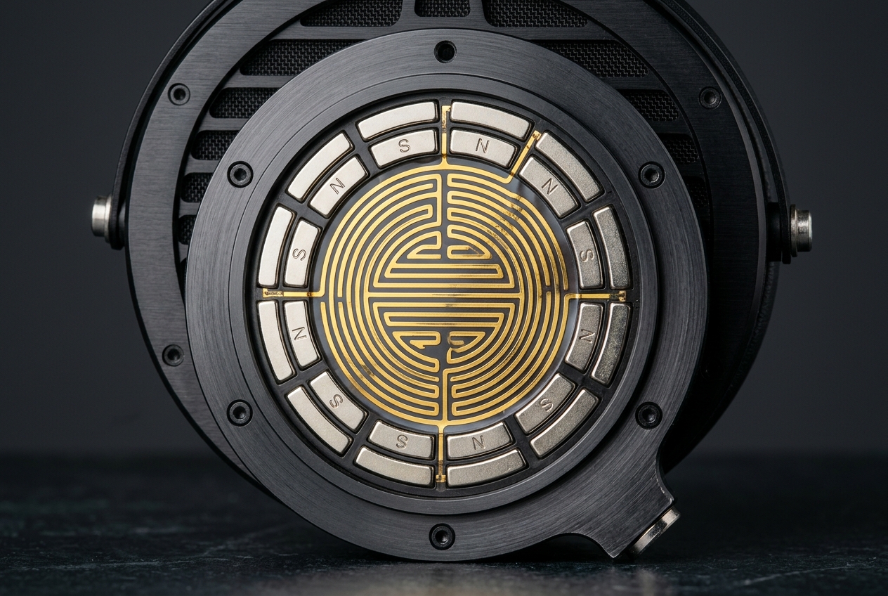
| Single-Sided 90° Discrete Halbach (N54) | 0.88 T | 1.8 mT | 68.5% (Rear Only) | ±0.75 mm | 0.05% |
| Double-Sided Opposed Halbach Array (Push-Pull) | 1.22 T | 0.6 mT | 48.0% | ±0.50 mm | 0.02% |
| Neo-Slit Micro-Perforated Single Stator | 0.46 T | 22.4 mT | 38.0% (Rear Only) | ±0.65 mm | 0.15% |
The quantitative parameters presented in the matrix above illuminate the stark engineering compromises governing planar magnetic headphone architectures. In a standard bilateral push-pull bar array, achieving an acceptable effective flux density of 0.58 Tesla requires packing thick bar magnets on both sides of the diaphragm. This restricts the acoustic open area to an alarming 42.5%, transforming the stator into an acoustic obstruction where high-frequency acoustic waves suffer internal diffraction, edge scattering, and severe acoustic cavity resonances. Furthermore, bilateral stator designs severely restrict excursion clearance ($X_{max} \approx \pm 0.55\text{ mm}$), capping low-frequency maximum SPL before voice-coil bottoming occurs.
Conversely, the single-sided 90° discrete Halbach array achieves an astounding 0.88 Tesla peak gap flux density—a 158% increase over the single-sided alternating bar design and a 51% increase over the bilateral push-pull array—while entirely eliminating the front stator. Because the front radiating face of the diaphragm experiences zero acoustic blockage (100% open aperture to the ear), and the rear stator channels achieve 68.5% acoustic open area due to the narrower bar geometries permitted by unilateral flux concentration, viscous air resistance drops exponentially. The stray external flux is simultaneously suppressed from 38.6 mT down to a negligible 1.8 mT at a 10 mm measurement plane, completely shielding nearby mobile electronics and preventing driver frame magnetization without requiring heavy steel flux return plates.
4. Mechanical Assembly, Magnetic Shear Forces, and Intrinsic Coercivity Margins
While the theoretical electromagnetic advantages of Halbach arrays are mathematically pristine, physical implementation in a high-performance headphone driver presents extraordinary mechanical and material engineering challenges. In a standard alternating bar array, adjacent magnets with opposite magnetic orientations ($N-S$) naturally attract each other along their lateral mating edges, assisting assembly fixturing. In a 90-degree Halbach array, however, adjacent elements reside at orthogonal $90^\circ$ dipole angles. The transverse ‘flux-guiding’ magnets experience ferocious repulsive forces and severe lateral shearing torques governed by Maxwell’s stress tensor:
$$\sigma_{ij} = \frac{1}{\mu_0} \left( B_i B_j – \frac{1}{2} \delta_{ij} B^2 \right)$$
The shear forces attempting to twist and eject the horizontal magnet blocks exceed several hundred newtons across a standard 85 mm planar driver stator. Assembling these arrays requires high-precision non-magnetic CNC-machined structural stators—typically fabricated from aerospace-grade 6061-T6 aluminum, grade 5 titanium, or high-modulus carbon-fiber matrix composites. Structural adhesives must exhibit extreme lap shear strength (>25 MPa) and high glass transition temperatures ($T_g > 130^\circ\text{C}$) to withstand continuous multi-axis mechanical stress and prevent microscopic creep under cyclic thermal loading when driven hard by balanced headphone amplifiers during intense audiophile listening sessions.
Equally perilous is the risk of localized irreversible demagnetization. Sintered Neodymium-Iron-Boron (NdFeB) grades with ultra-high remanence, such as N52 and N54 ($B_r \ge 1.45\text{ T}$), frequently exhibit lower intrinsic coercivity ($H_{cj} \approx 11\text{ to }14\text{ kOe}$). In a Halbach array, the horizontal flux-focusing elements route intense magnetic flux directly into the corners of adjacent transverse elements, subjecting those localized regions to severe reverse demagnetizing fields ($H_{rev}$). If the operating temperature within the headphone ear cup rises due to continuous voice-coil Joule heating ($I^2 R$), the operating point on the $B-H$ demagnetization curve shifts below the critical knee, causing permanent, catastrophic flux loss. To insulate against this failure mode, transducer engineers must specify dysprosium-doped, high-coercivity grades—such as N50SH or N52H ($H_{cj} \ge 21\text{ kOe}$, operating temperatures up to $150^\circ\text{C}$)—ensuring absolute magnetic stability under all transient operating states.
Furthermore, Neodymium is an electrically conductive intermetallic alloy with a low bulk resistivity ($\rho \approx 1.4 \times 10^{-6}\ \Omega\cdot\text{m}$). As high-frequency audio currents (10 kHz to 40 kHz) oscillate through the voice-coil serpentines, the dynamic magnetic field induces localized eddy currents (Foucault currents) within the conductive pole faces of the solid Halbach magnets. These micro-eddy currents generate opposing magnetic fields that induce high-frequency voice-coil inductance rise, acoustic damping, and subtle phase shifts. To eliminate high-frequency parasitic losses, elite transducer motors utilize segmented magnet laminations, high-resistivity soft magnetic composite (SMC) pole tips, or specialized vapor-deposited 5-micron Parylene-C dielectric passivation coatings.
5. Acoustic Radiation Impedance and Stator Cavity Viscous Squeeze-Film Losses
The micro-gap separating the planar diaphragm from the stator assembly ($d_{gap} \approx 0.45\text{ mm to }0.85\text{ mm}$) functions as a narrow fluidic channel governed by the linearized Navier-Stokes equations for compressible acoustic flow. As the tensioned membrane oscillates, it pumps air laterally across the magnet surfaces toward the open exit apertures. The interaction between fluid viscosity and the solid stator boundaries establishes an acoustic viscous boundary layer whose characteristic penetration depth $\delta_{visc}$ is dictated by acoustic frequency $\omega$ and air kinematic viscosity $\nu$:
$$\delta_{visc} = \sqrt{\frac{2\nu}{\omega}} = \sqrt{\frac{2\eta}{\rho_0 \omega}}$$
At an audio frequency of 1 kHz in standard atmospheric air ($\nu \approx 1.5 \times 10^{-5}\ \text{m}^2/\text{s}$), the boundary layer thickness is approximately $69\ \mu\text{m}$, contracting to $22\ \mu\text{m}$ at 10 kHz. In conventional bilateral push-pull headphones, where the diaphragm is hemmed in by dual stator grids, the confinement ratio between gap depth and boundary layer thickness generates severe squeeze-film air damping. This squeeze-film phenomenon manifests as a non-linear acoustic resistance ($R_{squeeze}$) and acoustic mass reactance ($M_{squeeze}$) that overdamps micro-transient settling, constricts dynamic headroom, and smears low-level reverberant decay.
The single-sided Halbach topology delivers an evolutionary leap in fluidic aerodynamics. Because the ear-facing side of the diaphragm is completely devoid of stators, the acoustic radiation impedance on the front face matches the pure characteristic acoustic impedance of free air ($Z_0 = \rho_0 c \approx 415\ \text{Pa}\cdot\text{s}/\text{m}$). The radiating membrane couples directly to the ear canal volume without undergoing cavity Helmholtz compression or slit-duct viscous drag. On the rear side, the concentrated flux of the Halbach array allows the stator magnets to be spaced further apart or contoured with parabolic aerodynamic profiles ($C_d \le 0.25$), radically reducing rear back-pressure and liberating diaphragm transient acceleration to reach its true mechanical limits.
6. Photolithographic Voice-Coil Topography and Spatial Gradient Matching
In a planar magnetic transducer, the conductive voice coil is not a wound cylindrical coil, but an intricate, planar serpentine circuit photolithographically etched onto an ultra-thin polymer substrate. For optimal Lorentz force coupling, the conductive traces must not be distributed uniformly across the membrane; instead, their spatial layout must mirror the exact Fourier harmonic distribution of the Halbach magnetic field.
As established by the spatial boundary equations, the vertical flux component $B_z(x)$ in a 90° discrete Halbach array peaks with alternating positive and negative values directly beneath the vertical ($90^\circ$ and $270^\circ$) magnet blocks, while dropping to zero directly beneath the centers of the horizontal ($0^\circ$ and $180^\circ$) flux-guiding blocks. Consequently, the forward-flowing voice-coil traces must align precisely within the positive $B_z$ zones, while the reverse-flowing return traces must align within the negative $B_z$ zones. The interstitial zones where $B_z \approx 0$ must remain completely bare of conductive metal. Any lateral photolithographic misalignment—even as minute as $\pm 25\ \mu\text{m}$ across an 80 mm membrane—causes the conductive traces to drift into the transverse horizontal flux field ($B_x$), generating parasitic shear stresses that induce membrane rocking modes, dynamic buckling, and severe second-harmonic distortion ($HD_2$).
Thermal expansion management introduces another critical design constraint. Aluminum voice-coil traces have a coefficient of thermal expansion (CTE) of $\alpha_{Al} \approx 23 \times 10^{-6}/\text{K}$, whereas a typical polyimide base substrate has a CTE of $\alpha_{PI} \approx 15 \times 10^{-6}/\text{K}$. Under continuous high-current transients, differential thermal expansion can cause microscopic delamination or membrane crinkling. In single-sided Halbach systems, heat dissipation is naturally biased toward the open front chamber. Transducer engineers counteract thermal shear by utilizing sub-micron copper-on-aluminum bi-metallic claddings, radiused trace turn-around knuckles, and perimeter tangential corrugation patterns that relieve radial hoop stress without disturbing diaphragm modal tension. These precision micro-fabrication methodologies are increasingly migrating from full-sized circumaural headphones into ultra-high-resolution planar in-ear monitors.
7. Electroacoustic Implementation Guidelines & Engineering Synthesis
- Spatial Wavelength Optimization (\(\lambda\)): Calibrate the 4-element Halbach magnetic wavelength between 3.2 mm and 4.4 mm. Pole pitches below 3.0 mm cause excessive near-field flux decay ($z_{pen} = \lambda / 2\pi$), causing the diaphragm to experience severe non-linear flux droop under high-excursion bass transients; pole pitches above 4.8 mm require excessively thick magnet blocks that restrict acoustic open area.
- Demagnetization Coercivity Safety Margin: Specify ultra-high intrinsic coercivity NdFeB alloys (minimum N50SH or N52H with \(H_{cj} \ge 21\text{ kOe}\) and maximum operating temperature \(T_{max} \ge 150^\circ\text{C}\)) to completely prevent localized irreversible thermal demagnetization driven by adjacent 90° orthogonal repelling poles and voice-coil Joule heating.
- Aerodynamic Stator Open Area: Maintain a rear stator acoustic open area greater than 65%, and bevel or radius the lateral edges of the Halbach magnet retainers with elliptical aerodynamic profiles (\(C_d \le 0.22\)) to suppress high-velocity air turbulence noise and prevent viscous squeeze-film boundary layer compression.
- Photolithographic Trace Alignment Tolerances: Enforce a strict photolithographic registration tolerance of \(\pm 15\ \mu\text{m}\) between the voice-coil serpentine centers and the stator vertical flux peaks (\(B_{z,max}\)) across the entire active diaphragm diameter to keep second-harmonic distortion (\(HD_2\)) suppressed below -66 dB (0.05%).
- Structural Assembly Mechanical Fixturing: Utilize non-ferromagnetic, high-rigidity stator materials (e.g., CNC-machined Grade 5 Titanium or high-modulus carbon-fiber matrix) coupled with aerospace-grade structural epoxies having a glass transition temperature \(T_g \ge 130^\circ\text{C}\) and lap shear strength \(\ge 25\text{ MPa}\) to resist continuous multi-axis magnetic shear torques across lifetime operating cycles.
The integration of Halbach array magnet topologies represents a watershed evolution in isodynamic headphone engineering, dismantling the historic compromise between electromagnetic motor efficiency and acoustic diffraction. By mastering the spatial Fourier harmonics of Klaus Halbach’s vector rotation, electroacoustic engineers can project an intense, highly linear 0.9 Tesla magnetic field exclusively into the active voice-coil plane while rendering the external rear field magnetically inert. This eliminates the need for heavy, resonance-prone steel back-plates while liberating the human listener’s ear from the phase smearing and comb-filtering distortions inherent to traditional bilateral push-pull stators.
When combined with sub-micron photolithographic serpentine alignment, advanced aerodynamic boundary geometries, and high-coercivity NdFeB metallurgy, the single-sided 90° Halbach planar transducer achieves an unrivaled electroacoustic profile: ruthless transient speed, imperceptible harmonic distortion, effortless acoustic dynamics, and pristine, holographic spatial imaging. As transducer modeling tools and micro-manufacturing tolerances continue to advance, unilateral flux concentration stands as the definitive blueprint for the next generation of reference-grade planar magnetic listening.
Discuss more about this, FAQ, Announcements and Miscellaneous, over on our community.

Leave a Reply